
Designing a High-Efficiency Buck/Boost Converter with the onsemi NCP3065DR2G
The demand for flexible and efficient power management solutions is paramount in modern electronic design, especially for battery-powered applications where input voltage can vary above and below the desired output. A buck/boost switching regulator provides this essential capability, and the onsemi NCP3065DR2G offers a robust and cost-effective foundation for such a design. This article outlines the key considerations for designing a high-efficiency, continuous conduction mode (CCM) buck/boost converter using this versatile IC.
The NCP3065DR2G is a monolithic fixed-frequency switching regulator that can be configured for buck, boost, or inverting topologies. Its internal circuitry includes a temperature-compensated voltage reference, a duty cycle controlled oscillator, and a high-gain error amplifier. Crucially, it features a high-output switch capable of sourcing up to 1.5 A of peak current, making it suitable for moderate power applications. Operating at an oscillator frequency of up to 250 kHz allows for a good balance between component size and switching losses.
Design Philosophy for High Efficiency
Achieving high efficiency in a buck/boost converter requires meticulous attention to several key areas:
1. Inductor Selection: The inductor is the heart of the converter. Its value must be chosen to ensure continuous conduction mode (CCM) across the expected load range, which minimizes ripple current and reduces RMS losses. A larger inductance value decreases ripple but can impact transient response. The inductor must also have a low DC resistance (DCR) and a current rating significantly higher than the maximum peak current to avoid saturation.
2. Power MOSFET and Diode: While the NCP3065 contains an internal bipolar switch, for higher efficiency—especially at higher currents—an external low-side N-channel MOSFET is highly recommended for the switching element. This drastically reduces the saturation voltage (Vce(sat)) losses associated with the internal bipolar transistor. Similarly, using a Schottky diode for the catch/boost diode is essential due to its low forward voltage (Vf), which minimizes power loss during freewheeling phases.
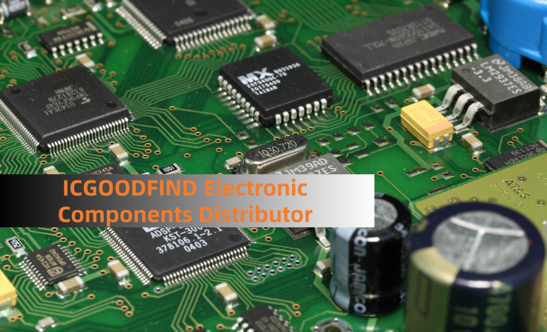
3. Capacitor Selection: Low-Equivalent Series Resistance (ESR) capacitors are non-negotiable for both input and output filtering. High ESR increases ripple voltage and causes significant I²R power losses. Ceramic capacitors (X5R or X7R) are preferred for their exceptionally low ESR, which helps in achieving a clean output voltage and enhances overall efficiency.
4. Feedback and Compensation: The feedback network, typically a resistor divider, must be precise and stable. The error amplifier within the NCP3065 requires proper compensation to ensure loop stability. The compensation network, usually an RC circuit connected from the output of the error amplifier (COMP pin) to ground, must be tailored to the chosen inductor and output capacitors to prevent oscillations and ensure good transient performance.
A Practical Implementation Example
Consider a design requirement to provide a stable 5V output from a lithium-ion battery input ranging from 3.0V to 4.2V. This scenario, where VIN can be both below and above VOUT, is a classic use case for a buck/boost regulator.
Topology: A single-inductor, four-switch (H-bridge) topology offers the best performance but increases complexity. A more straightforward approach using the NCP3065 involves a single inductor with a switch and diode configuration that can be toggled between buck and boost modes based on the input voltage.
Control Logic: While the NCP3065 itself is not an automatic buck-boost controller, its feedback mechanism can be leveraged. By comparing the input voltage (via a resistor divider) to the feedback reference, external logic can be used to switch the configuration of the IC and external components between buck and boost modes, ensuring a seamless transition.
Layout Considerations: A proper PCB layout is critical for switching regulators. The paths carrying high switching currents—specifically the connections from the input capacitor to the IC's switch pin and to the catch diode and inductor—must be as short and wide as possible to minimize parasitic inductance and electromagnetic interference (EMI). A solid ground plane is essential for noise reduction.
ICGOODFIND: The onsemi NCP3065DR2G provides a flexible and economical core for building non-synchronous buck/boost converters. By carefully selecting external components—notably a low-Rds(on) MOSFET and a low-Vf Schottky diode—and adhering to strict PCB layout practices, designers can achieve a highly efficient and reliable power supply capable of handling widely varying input voltages, making it an excellent choice for portable and battery-operated devices.
Keywords: Buck/Boost Converter, NCP3065DR2G, High-Efficiency Design, Continuous Conduction Mode (CCM), Schottky Diode

